Friday, November 24, 2017

Flip32/Naze quad controller hacking

I've always wanted to incorporate an inexpensive quad flight controller into this project.  I though I could use it as an autopilot.  Having hacked the Multiwii Serial Protocol (MSP) I now have some much bigger ideas about what it can do.

First... what is a quad controller... Here's a spec sheet for a $30 quad controller:

Flip32+ NAZE 32 10DOF Flight Control board
  • 36x36 mm
  • 3-axis MEMS gyro + accelerometer (MPU6050)
  • 3-axis magnetometer (HMC5883L)*
  • Pressure sensor (MS5611)*
  • Flexible motor outputs, support various airframe types
  • Up to 8 ch RC input-supports standard receivers(PWM), PPM Sum receiver
  • Battery voltage monitoring (up to 16vdc)
  • Modern 32-bit processor running at 3.3V/72MHz(STM32F103CB).
  • MultiWii-based configuration software for easy setup

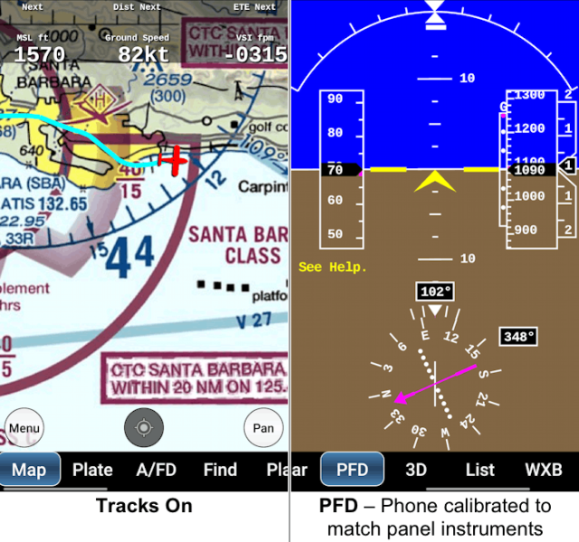
This is a TON of sensors and a serious processors already supported by somebody else's firmware (I used Cleanflight) and it outputs on a USB VFR direct to an android tablet  running Avare open-source with updates to support it.

So to re-state the list above as fully supported features by somebody else;

  • IMU - Roll, Pitch, Magnetic Heading, Altitude, Variometer (vertical speed), Groundspeed
  • GPS - Supports interfacing with a GPS 
  • AutoPilot - 3-axis Giant-Scale R/C servo ready.  Built in heading-hold, altitude-hold, fly-to-position.
  • Precise Sonar Altitude HCSR04 ( <3.8-meters AGL for auto-land)
  • Battery Voltage

What it does not do that an aircraft would need...
  • Airspeed
  • Angle of Attack
  • Oil Temp
  • Oil Pressure
  • Cylinder Head Temp (x4 or x6)
  • Exhaust Gas Temp (x4 or x6)
  • Fuel Pressure
  • Fuel Flow
  • Fuel Level (x2-4)
  • Ammeter
  • Outside Air Temp

How do you communicate with the controller?  MSP.  For my tests I just wrote a simple C# console app that opened the serial port, sent an MSP_ATTITUDE request and extracted the response as pitch, roll and heading.

Sample:

bufView[0] = 36; // $
bufView[1] = 77; // M
bufView[2] = 60; // <.
bufView[3] = 0; // data length
bufView[4] = 108; // MSP_ATTITUDE
bufView[5] = (byte)(bufView[3] ^ bufView[4]); // checksum

do
{


port.Write(bufView, 0, 6);

System.Threading.Thread.Sleep(1);


// Preamble
if ('$' != port.ReadByte() ||
'M' != port.ReadByte() ||
'>' != port.ReadByte())
continue;

var length = port.ReadByte();
var codeT = port.ReadByte();
var buffT = new byte[length];

port.Read(buffT, 0, length);

var roll = (Int16)(buffT[0] + 256 * buffT[1]) / 10.0;
var pitch = (Int16)(buffT[2] + 256 * buffT[3]) / 10.0;
var yaw = (Int16)(buffT[4] + 256 * buffT[5]);

var crcCalc = (byte)(buffT.Aggregate((a, b) => (byte)(a ^ b)) ^ 
              length ^ codeT);

if (crcCalc != port.ReadByte())
  continue;

Console.WriteLine($"{roll}, {pitch}, {yaw}");

System.Threading.Thread.Sleep(200);
} while (true);


This is really just test code, but it shows how simple it is to send a request and get back some very basic data.  The full MSP spec is here.  This has a lot of possibilities and I will likely incorporate the controller into even a basic system because it adds so much for so little added complexity and cost.

Given the information I've learned, the system design is dramatically simpler...


Friday, August 11, 2017

WIP

I concously set this project aside about 18mo ago to concentrate on an airplane project.  That project is winding down.  I attended #OSH17 and I was kinda shocked nobody else is trying to do anything like this.  Perhaps the fact that it's non-commercial?  At any rate, the idea stays the same, open source DIY project to build your own flight instruments for a basic VFR aircraft that you can integrate with either a very basic dedicated display and/or a panel mounted tablet or an economical panel mounted Android Car Stereo.  I am a fan of the open-source Avare flight software and that community is very active and receptive to pull requests (changes).  I am quite confident if I developed this board and wrote the updates to display engine data, they would add the tab for engine/air data.  This would make an excellent poor-man's ($300?) EFIS


This is Avare... I would add flight data to the PFD display above and a new tab for engine data.

Let's get caught up....


It's quite basic, and I haven't tried flight yet. I recall when I set this aside, I had it mostly working on the bench, but it need further refinement and flight testing/debugging.

The core of it is up to 8 channels of analog input with handy through holes for pull-up/down resistors to match the most resistance sensor (OilT, OilP,CHT,EGT,OAT,MP...). For more complicated sensors that require special component, I have two I2C inputs. There are lots of really cheap I2C modules for pressure, inertia/gyros and magnetic compass. Basically you can build your own air/engine data collector.

Let me know what you think. I have a few extra boards I'd send to anyone who's serious and commits to contributing.

Here's the GitHub repo on the very basic LCD display version of this.

https://github.com/bruceme/SportVFR

Thursday, June 30, 2016

Sport Air/Engine Data Collector

So I've written a new "firmware" (yeah it's just an Arduino sketch) based on the old SportVFR sketch.  This is designed specifically to be a generic data collector/emitter.  The idea is that SportVFR board when paired with an ATMega32U4 Pro Micro dev board is a multi-purpose data collection tool.

Here's how it works.  There are 25 "Channels", 3..21 are numbered after the actual channel (see picture)


0,1,11-13,16,22-24 are not usable as such.  22-24 are "virtual" and represent the Tachometer, Altimeter and Compass virtual output channels.

It is entirely commanded externally via 9600 baud serial.

Commands:
* NAME- Name channel
^ Val - Set Max
v Val - Set Min
< Val - Set channel value (for output)

All channel configurations are saved into EEPROM and are restored on reboot.

Channel names are 4 character and the first denotes its purpose.


Channel 1st character enumeration:

> Digital Input
$ PWM Output
~ Analog Input
< Digital Input
^ Input w/Pull-Up resistor
| Virtual (for internal only, don't use)

Overall grammar:

{MsgId}{Command}{Channel},{Parameter}

Example:

1*1,~TST    Names channel 1 to "~TST" which an analog input field  
3^2,100       Calibrate max 100 is the mapped output value of current reading

For its part the device serially dumps the polled data in this format;

-HDR-<TST-DAT-32

Here's the CodeBender Source

Monday, June 27, 2016

Avare update and Pitch

Early on in the AP idea, I thought I'd need a standard pitch servo for the AP function.  I've discussed and I'd like to try using the pitch trim to drive the hand-flown trim as well as the vertical autopilot functioning.  A good R/C servo is strong enough to set the tab and fast enough to control the pitch axis.  So I'm going to start there.

Avare..  I've posted to the group and found they are very receptive to the changes I've proposed.  I'm going to make my changes to that project, either directly or through an Avare-aware Add-On.  Either way, it's a good Android app platform to start from.  It already supports much of the functionality I'm looking to leverage.

Wednesday, June 22, 2016

How's this all going to work together?

I've been throwing around a lot of boxes, boards and ideas... but I hadn't really technically nailed down how all these parts fit together and if they do actually fit together.  Good news... it does, and very simply and I can leverage existing software for 90% of the functionality.

The key to this are two Arduino Mini ATMega32U4 based controllers.  The first is one is obvious... SportVFR's, collecting engine and airspeed data.  That data is sent to Android device via serial communications on a dedicated USB.  This could potentially be Bluetooth, that is a future development.

As I started composing this architecture, I found I was missing two interfaces... First, the pilot's joystick input to the CarPC (programmable stick buttons).  Second, the interface to the Naze was not very robust.  Sure, I can connect via USB and run in a pseudo config/command mode.  But ideally, you want a dedicated processor feeding serial inputs to the Naze acting as though it is a R/C receiver.  This is perfect for translating the high-level AP commands form the Android to the Naze... I'll have a post on the AP commanding next.

Saturday, June 18, 2016

More AP specifics

Controller: Naze32

Firmware: CleanFlight iNav (specifically for UAV with improved navigation function built-in)

Interface: Multiwii Serial Protocol

So here's roughly how it will integrate... I'll flash and install the cleanflight iNav to the Naze32.  I'll use cleanflight iNav configuration software to setup the controller.  The Controller will not take any servo channel inputs, but it will drive the aileron trim servo and the pitch stepper servo via a RC PWM to 4-wire Stepper translation IC (probably arduino).

The Android 4.4 CarPC will have a dedicated permanent USB connection to the Naze32.   I'll run the configuration software on the CarPC.  I'll write my own Autopilot command app that will send Wii Serial  command (MSP_SET_RAW_RC) to the Naze32 via the USB.  These command will engage/disengage the AP modes on the Naze32, trim the aileron (when disengaged) and steer the AP for navigation mode.

Thursday, June 16, 2016

Let there be Autopilot!

Back in 2002-3 I experimented with a roll-axis autopilot that used a single axis solid state gyro on my RV-3.  Ultimately the project failed for several reasons.  But mostly the technology was not ready for my level of knowledge.  It is no-longer that way.  You easily access 10-dof Quad Copter controller boards which can be reconfigured for the larger mass and inertia of full-scale.


Roll/Pitch - Heavy-duty sealed waterproof metal gear digital R/C Servo.  Connected to an aileron/elevator trim tab.


Integration is where it gets messy.   So you have an Android Car PC, which has USB output.  You can directly connect the Quad Controller to the Android PC.  Normally this would be done to run the setup of the quad controller.  But it could be permanently connected and there should be a way to command the quad board between normal flight and autopilot mode from the USB via this configuration mode.  Normally this would happen via an Auxiliary transmitter channel.  Furthermore, there should be means to steer the autopilot for navigation on that same usb connection.  There are three AP modes; off, steer and hold.

Steer - Generally keep the vehicle flying upright, but use the various channel inputs to direct the vehicle

Hold - Ignore the inputs and keep the last Altitude and Heading.

I can see both of these modes being utilized by the high level Autopilot function in the EFIS.

The roll axis can be directly controlled by the quad controller.  When AP-mode is disengaged it will act as roll-trim getting input from the Arduino PC via USB connection.

The pitch axis will require a controller that can translate the servo output PWM signal to stepper motor.  I'd build a small board to do that.  Probably us a Arduino Mini or an ATTiny88.


At the end of the day.. What I want the pilot to have is completely naturally intuitive integrated autopilot.  So ahead of time, you plan your flight on a third party Android app.  We'll upload the plan to our app.

When you take off at 1000 AGL, an AP-FP button pops in the corner.  You press it,  it uses your airspeed to drive climb rate (constant airspeed) and steers you on flight plan.  Let's say you're not ready to go on flight plan heading yet.  You fight the roll to wings level.  A button pops... AP-HH.  Press it, your on heading hold... still climbing.  You fight the servo and push the nose over... button pops AP-AH, altitude hold.

So now you're flying along.  And there's Class-C airspace at your altitude.  Pop-up... AP Airspace [Through] [Over] [Under] [Left] [Right] (This would be icons as depicted below, not words).

AP: Airspace
       ^
    < 0 >
       v

Flying along.. ADS-B finds a traffic conflict

AP: Traffic
       ^
    <   [>]     [recomended]
       v

Keep flying and you get to the vertical intercept.  Where you need to descend.  Pop up, AP-DES.